3D Printed Curta Part III
- Marcus Wu
- 3 dprinting , Curta
- May 12, 2015
Modeling Refinements
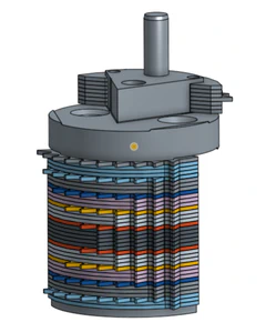
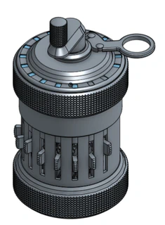
In part 2 I finished modeling the parts for the Curta. Now I have completed an assembly of all of the parts in OnShape. For the most part I added mates that allow the proper movement of the pieces, but in some circumstances I had to limit the movement so the assembly didn’t suffer. While the mates allow movement, there is no collision detection or other relationships between the parts, so sliding a digit selector does not turn the selector shaft or move the transmission gear.
Despite that, it was a good exercise. I found a number of problems that have now been solved. The digit selector knobs were not the right size – the engineering drawings show all of the knobs being machined from one piece. I did not account for the material that would be cut away when the knobs were cut apart. The step drum parts did not want to mate correctly and I had to manually adjust them because the edges of the teeth were intersecting the transmission gear sleeves. There were a few other similar issues as well.


3D Printer Accuracy vs Resolution
I first set out to figure out what clearance between a hole and a shaft would lead to different mechanical fit types. I printed a series of holes and shafts where the shafts varied in diameter while the holes were all the same. The range was fairly large with a pretty course step (0.05mm). I only got about half-way through fitting the holes into the shafts before I ended up with a forced fit. I believe I printed these at a 0.23 mm layer height at a tame speed for my printer of 3000 mm/s. Here are the (very basic) results:
- 0.35 mm – Loose sliding fit
- 0.3 mm – Sliding fit
- 0.25 mm – Tightish transition fit. (pressed into place by hand; removable by hand; twists with some effort)
- 0.2 mm – Forced fit. (pressed into place by hand; cannot remove by hand; cannot twist; removal with pliers damaged the parts)
While doing some research on hole and shaft tolerances, I came across an article discussing accuracy vs resolution . The difference is something akin to precision vs accuracy. A printer can print at a high resolution, but if the layers it deposits vary in width or position a lot, it has a low accuracy.
That article led me to the thought that instead of adjusting all my parts by a larger tolerance, my tolerances should be the same as the engineering drawings, but I should also account for accuracy by subtracting it from shafts or adding it to holes (or half and half).
To test this, I devised multiple test prints. The first was to find my printer’s accuracy. Again I printed a series of holes and shafts where the shafts varied in diameter. This time I started at 0.2 mm clearance and increased the gap by 0.01 at each step while also adding in a 0.02 mm for the maximum H7/h6 mechanical fit tolerance. I ran these prints at a smaller layer height of 0.1mm. The one that fits best should indicate my printer’s accuracy.
After printing the test, the smallest accuracy clearance (0.2 mm + 0.02mm fit tolerance) turned out to provide the closest sliding fit after the pieces were worked together a little bit. That tells me that at 0.2mm I am clearing most of the ridges that the 3D printing process creates, but there are a few outliers (mainly where there are joints) which get worn down as the parts are moved.
While it is probably not 100% correct, for my purposes I am going to call my printer’s accuracy +/- 0.1 mm (or +/- 0.2 mm counting two walls – one on either side of the shaft).
Next I printed some smaller fit tolerances with the same clearance for accuracy. I used the following fits:
- H7/h6 for an LC2 fit (this was the same as earlier to have a comparison)
- H7/js6 for an LT1 fit
- H7/k6 for an LT2 fit
I was hoping for a noticeable difference in how these fit, but they all have similar resistance after working the parts together which is probably the problem – any difference in width is worn away.
These tests give me an idea for how to proceed and give me a starting point to run some tests with Shapeways.
I also printed the same test on the printer at my office, but it is not as finely tuned. The results showed that difference with pegs that were visibly not as straight vertically. They did not fit as well as a result and got stuck when I tried to push the peg through.

